
diffraction into the "street canyon" below.1⁄ r 4 propagation over the rooftop landscape.

This is made possible by a combination of the following effects: Designs for microwave formerly used 4⁄ 3 earth radius to compute clearances along the path.Īlthough the frequencies used by mobile phones (cell phones) are in the line-of-sight range, they still function in cities. It is important to take into account the curvature of the Earth for calculation of line-of-sight paths from maps, when a direct visual fix cannot be made. See also Non-line-of-sight propagation for more on impairments in propagation. This effect can be reduced by raising either or both antennas further from the ground: The reduction in loss achieved is known as height gain. Reflected radiation from the surface of the surrounding ground or salt water can also either cancel out or enhance the direct signal.
PPT ON ANTENNA AND WAVE PROPAGATION FREE
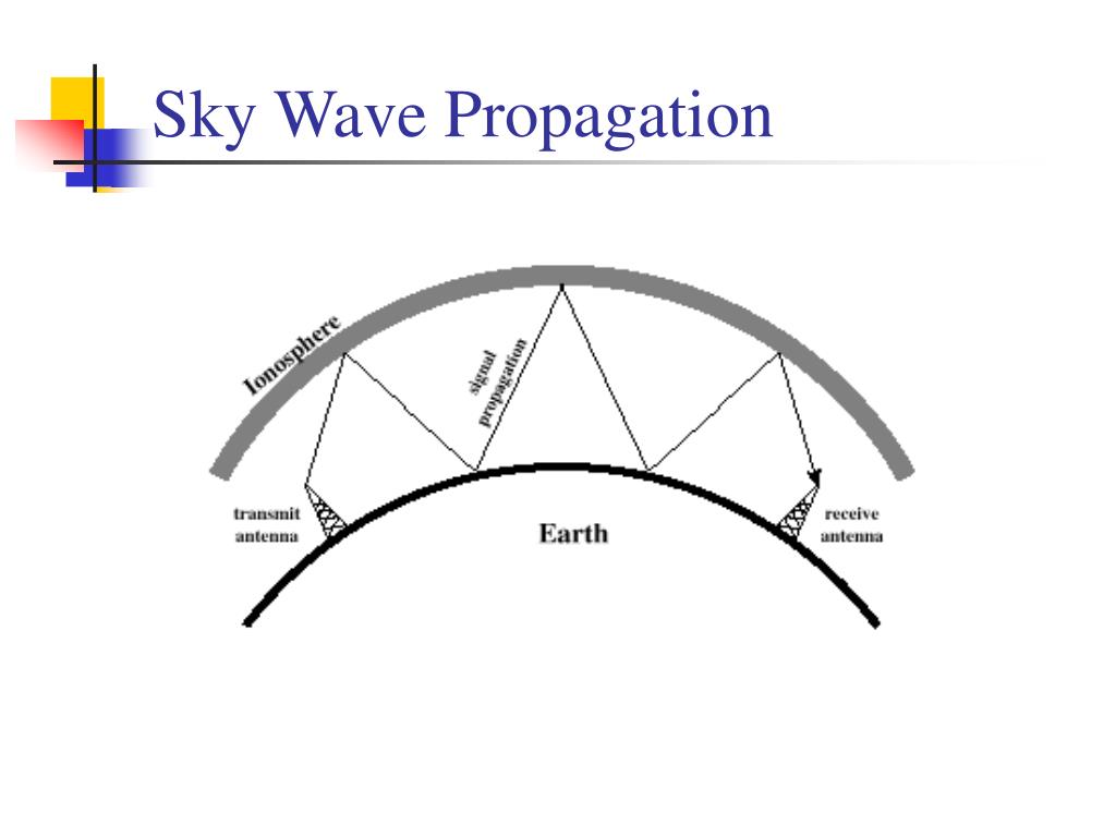
For the best propagation, a volume known as the first Fresnel zone should be free of obstructions. The presence of objects not in the direct line-of-sight can cause diffraction effects that disrupt radio transmissions. Low-powered microwave transmitters can be foiled by tree branches, or even heavy rain or snow. Objects within the Fresnel zone can disturb line of sight propagation even if they don't block the geometric line between antennas. Broadcast FM radio, at comparatively low frequencies of around 100 MHz, are less affected by the presence of buildings and forests. In practice, the propagation characteristics of these radio waves vary substantially depending on the exact frequency and the strength of the transmitted signal (a function of both the transmitter and the antenna characteristics). The farthest possible point of propagation is referred to as the "radio horizon". Therefore, since the ability to visually see a transmitting antenna (disregarding the limitations of the eye's resolution) roughly corresponds to the ability to receive a radio signal from it, the propagation characteristic at these frequencies is called "line-of-sight". Thus, any obstruction between the transmitting antenna ( transmitter) and the receiving antenna ( receiver) will block the signal, just like the light that the eye may sense. However, at frequencies above 30 MHz ( VHF and higher) and in lower levels of the atmosphere, neither of these effects are significant. Additionally, frequencies in the shortwave bands between approximately 1 and 30 MHz, can be refracted back to Earth by the ionosphere, called skywave or "skip" propagation, thus giving radio transmissions in this range a potentially global reach.

This enables AM radio stations to transmit beyond the horizon. In contrast to line-of-sight propagation, at low frequency (below approximately 3 MHz) due to diffraction, radio waves can travel as ground waves, which follow the contour of the Earth. The rays or waves may be diffracted, refracted, reflected, or absorbed by the atmosphere and obstructions with material and generally cannot travel over the horizon or behind obstacles. Electromagnetic transmission includes light emissions traveling in a straight line. Line-of-sight propagation is a characteristic of electromagnetic radiation or acoustic wave propagation which means waves travel in a direct path from the source to the receiver.


 0 kommentar(er)
